Penny Press Machine
Designed and modeled a fully functional penny press machine in Autodesk Inventor, applying GD&T and assembly principles to create a manufacturable design for the MET102 Simple Machines Project.
Mechanical Designer
As part of the Simple Machines Project (MET 102 – Purdue University), I was given full freedom to design and model a complete mechanical system that demonstrated multiple simple-machine principles. I chose to create a penny press machine—a small mechanical device that flattens and embosses a coin—because it combines gears, levers, axles, and screws into a single cohesive mechanism. This project required careful attention to mechanical relationships, realistic motion, and manufacturability from the ground up.
Problem
As part of the Simple Machines Project (MET 102 – Purdue University), I was given full freedom to design and model a complete mechanical system that demonstrated multiple simple-machine principles. I chose to create a penny press machine—a small mechanical device that flattens and embosses a coin—because it combines gears, levers, axles, and screws into a single cohesive mechanism. This project required careful attention to mechanical relationships, realistic motion, and manufacturability from the ground up.
Process
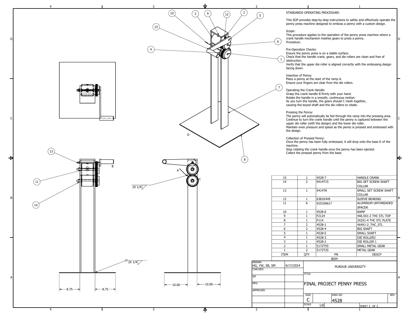
I began by sketching mechanical concepts for the gear train, crank arm, and press shaft, selecting ratios that would provide sufficient torque while maintaining ergonomic handle rotation. Using Autodesk Inventor, I modeled each component from scratch, ensuring proper constraints and clearances between moving parts.
To achieve assembly precision, I applied Geometric Dimensioning and Tolerancing (GD&T) to control parallelism, flatness, and runout across shafts and bearing seats. I also added weld symbols and callouts to define structural joints on the machine’s base frame, showing how the design could be fabricated in a real shop setting.
Each subassembly—gear train, roller assembly, and press mechanism—was fully constrained and animated to verify mechanical motion. The design process emphasized design-for-manufacture, ensuring all parts could be machined, laser-cut, or welded using standard shop processes.
Finally, I performed motion and interference analysis within Autodesk Inventor to confirm proper meshing of gears, alignment of shafts, and full range of lever motion without collision. This step ensured the mechanical system could operate smoothly and safely when manufactured, reflecting real-world functional behavior.

Prototype / Deliverables
3D CAD Model: A complete, fully constrained assembly showing all interacting parts.
Detailed Drawings: Dimensioned component and assembly drawings with GD&T tolerances and material specifications.
Weld Documentation: Welding spots and joint symbols defined on the base assembly drawing.
Bill of Materials (BOM): Comprehensive part list with identifiers, quantities, and materials.
Outcome & Takeaways
The completed design functioned as a fully modeled, manufacturable mechanical system within Autodesk Inventor. This project significantly strengthened my understanding of mechanical design fundamentals, design for assembly, and manufacturing documentation practices. It was an early hands-on experience in transforming creative ideas into precise, buildable engineering models—a skill set I continue to apply in more complex robotics and automation projects.